Technical Specifications
Composite Steel Beam Design software designs and checks encased and composite beams using ASD and LRFD design codes.
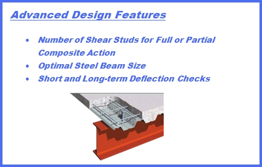
Both wide-flange and channel sections can be designed for full or partial composite action. Design considerations include shored /unshored construction, deflection checks, slab reinforcement at negative moments and more.
- Designs and checks using both ASD and RFD design codes.
- Beams can be wide flanges or channels.
- End conditions include pinned supports, fixed supports and cantilevers.
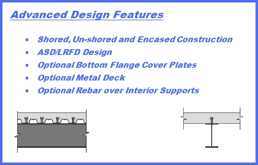
- Beams can be Non-composite, Encased-Unshored, Encased-Shored, Composite-Unshored and Composite-Shored.
- Slabs can be designed with or without a metal deck.
- Both Long-term and Short-term deflections are computed.
- Slab reinforcement over supports can be input to accommodate negative moments due to continuity.
- Cover plates can be added to the bottom flange to increase the section’s capacity.
- Load input includes concentrated, uniform, linear and triangular force distributions. End moments can be input to account for continuous spans.
- User-defined load combinations.
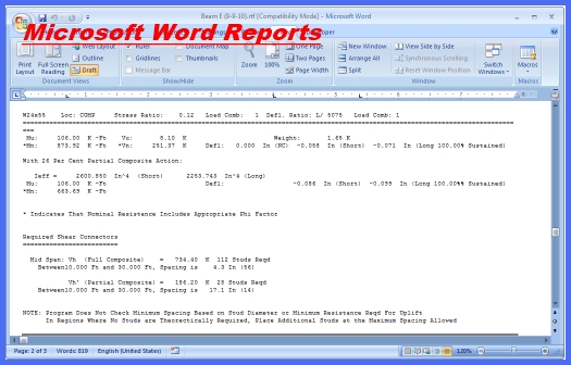
- Reports are in Microsoft Rich Text Format, which works with Microsoft Word and is recognized by nearly every word processor.
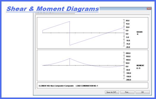
- Printable shear and moment diagrams.
- US customary and metric units.